9 Results
View results:
Sort by:

The goal of using the RFEM 6 and Blender with the Bullet Constraints Builder add-on is to obtain a graphical representation of the collapse of a model based on real data of physical properties. RFEM 6 serves as the source of geometry and data for the simulation. This is another example of why it is important to maintain our programs as so-called BIM Open, in order to achieve collaboration across software domains.

The Construction Stages Analysis (CSA) add-on allows for the design of member, surface, and solid structures in RFEM 6 considering the specific construction stages associated with the construction process. This is important since buildings are not constructed all at once, but by gradually combining individual structural parts. The single steps in which structural elements, as well as loads, are added to the building are called construction stages, whereas the process itself is called a construction process.
Thus, the final state of the structure is available upon completion of the construction process; that is, all the construction stages. For some structures, the influence of the construction process (that is, all the individual construction stages) might be significant and it should be considered so that errors in the calculation are avoided. A general overview of the CSA add-on is given in the Knowledge Base article titled “Consideration of Construction Stages in RFEM 6”.

The punching shear design, in line with EN 1992-1-1, should be performed for slabs with a concentrated load or reaction. The node where the design of punching shear resistance is performed (that is, where there is a punching problem) is called a node of punching shear. The concentrated load at these nodes can be introduced by columns, concentrated force, or nodal supports. The end of the linear load introduction on slabs is also regarded as a concentrated load and therefore, the shear resistance at wall ends, wall corners, and ends or corners of line loads and line supports should be controlled as well.

In order to create a surface model with failing supports close to reality, an option called "Failure if contact perpendicular to surfaces failed" is available in RFEM 5 for contact solids under "Contact Parallel to Surfaces".
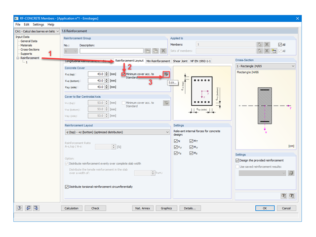
This article deals with the protection of reinforcement against corrosion defined according to EN 1992-1-1, also called concrete cover. The purpose of this article is to show how very many parameters defined in the Eurocodes for concrete reinforcements are considered in the RFEM structural analysis software.
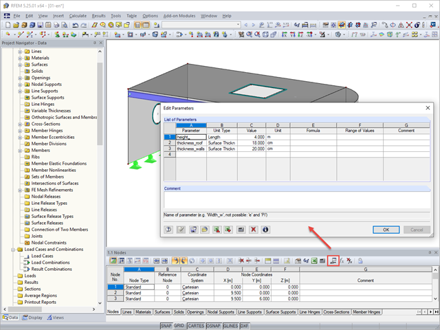
Parameterized entries provide the engineer with an efficiency-increasing tool. This allows entering structural and loading data so that they depend on certain variables. These variables (for example, length, width, live load, and so on) are called parameters.

When introducing and transferring horizontal loads such as wind or seismic loads, increasing difficulties arise in 3D models. To avoid such issues, some standards (for example, ASCE 7, NBC) require the simplification of the model using diaphragms that distribute the horizontal loads to structural components transferring loads, but cannot transfer bending themselves (called "Diaphragm").

Buckling analysis according to the effective width method or the reduced stress method is based on the determination of the system critical load, hereinafter called LBA (linear buckling analysis). This article explains the analytical calculation of the critical load factor as well as utilization of the finite element method (FEM).
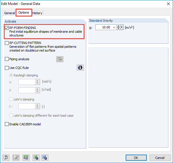
The RF-FORM-FINDING add-on module determines equilibrium shapes of membrane and cable elements in RFEM. In this calculation process, the program searches for such geometric position where the surface stress/prestress of membranes and cables is in equilibrium with natural and geometric boundary conditions. This process is called form-finding (hereinafter referred to as FF). The FF calculation can be activated in RFEM globally in the "General Data" of a model, "Options" tab. After selecting the corresponding option, a new load case or a calculation process called RF-FORM-FINDING is created in RFEM. An additional FF parameter is available for defining surface stress and prestress when entering cables and membranes. By activating the FF option, the program always starts the form-finding process before the pure structural calculation of internal forces, deformation, eigenvalues, etc., and generates a corresponding prestressed model for further analysis.